PCB X-Ray Inspection 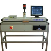
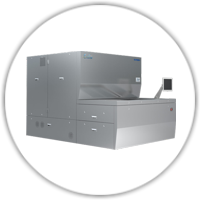
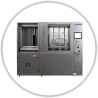
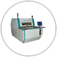
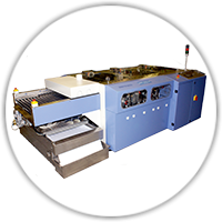
X-CHECK 310 MF is an X-Ray inspection desk for Multi-Layer panels, before and after the drilling process. The inspection of overlapped targets before drilling is to avoid to drill panels with high misalignment between the internal layers. After drilling, the use of X-Check 310 MF allows to evaluate the centering errors between holes and the relative pad. X-CHECK 310 MF is an evolution of previous model 300.
It is built with a fully shielded robust structure, which contains and holds:
- Micro focus X-Ray source to allow vision of minimum details.
- High sensitivity CCD camera with integrated X-Ray scintillator Camera controller allowing image integration (noise reduction), electronic zoom x 2 and CCD over exposure, which gives bright images also in case of high panel thickness.
- P.C. (Win XP) integrating hardware and software for capture and elaboration of the images, measurements and X-Ray control.
- The P.C., which is equipped with 15" LCD monitor, can be connected to the LAN to share the collected images asx-check documentation of the process quality.
- Laser or photographic printers also can be added as options.
- The working plane, which holds the panel, has been made more accessible respect to previous model, by retracting the upper plane, in order to allow better manipulation of the panel under inspection. The space between the panel holding plane and the upper plane also has been increased to 25 mm, in order to allow inspection of multiplayer panels, pinned with their backup panel.
X-Ray Control
A dedicated software application shows, with a simple click the X-Ray control Panel, which permits to adjust the KV, to display the actual KV and mA values, to display alarms, which are connected to risky conditions for the operator and the equipments.
The X-ray control panel can be hidden with another simple click when necessary, in order to grant the functionalities connected to the inspection job.
In order to maximise the X-ray tube life and efficiency, the control software sets automatically the anode current (mA) depending on the KV setting and the tube mA/KV characteristic. To the same aim, the software starts automatically the proper warm-up cycle, when required by the inactivity time of the X-ray source.
Getting Images & Measuring
By pressing the foot switch, the X-rays are turned ON, and within 2 sec the image appears. This is enough for a simple visual evaluation.
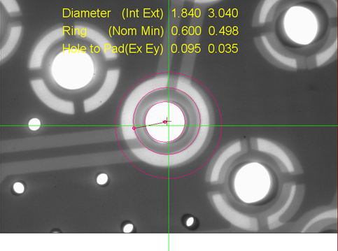
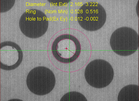
Anyway, the camera controller and the X-Check software offer a number of functions for image elaboration in difficult cases. In particular, frame Integration and CCD time integration are very powerful. When the image is "frozen", the Measure menu permits to check the hole to pad centring errors (Fig. 2) or straight lines to measure distances.
Then the image can be stored on the H.D. or printed out with or without the measurements in overlay. Quad image printing (four corners) is also available.
Safety
The operator and the environment are protected against X-radiation leakage by means of flexible lead-rubber curtains all around to the camera housing and the exposure room.
These offer full protection against X-Ray emission through the frontal, rear and side openings. The flexible curtains must be changed periodically, and to this aim, they can be easily accessed by removing the upper plate, which holds the cylindrical camera housing.
In addition, a dedicated circuitry inhibits the X-ray emission when the circuit of the signalling lamp is interrupted (lamp filament burnt), according to the existing laws Because of X-Ray presence, the equipment is supplied with a Radio Protection Certificate. This is released by a QUALIFYED EXPERT and it lists the radiation leakage measurements made on the specific equipment, according to EURATOM directives 80/836, 84/466, 84/467, 89/618, 90/641, 92/3, which concern ionising radiations.
Since the X-Ray leakage is less than 1 µSv/h at any point of the machine envelope, the operator is considered not exposed person. This means that because of the efficiency of the shielding system, there is no need of wearing the exposure badge for periodical check. The customer must simply declare the detention of an X-Ray equipment to the local Safety Department according to the local laws. All the components are CE compliant.
ADVANTAGES
- Powerfull userfriendly software
- Very detailed image (Fein Focus)
- Bright pictures even with thick panels
- PC for storing and printing measurement data
- Easy to connect to local network
- Very userfriendly software
PANEL FEATURES
- Max. panel dimensions: 700 x 600mm
- Min. panel dimensions: 300 x 200mm
- Panel thickness: 0,1 - 6mm
MACHINE FEATURES
- Electrical supply voltage: 220V – 50/60Hz
- Electrical power consumption: 600W
- Size: L 520mm x W 1240mm x H 1400mm
- X-Ray generator (Fein Focus)
- Max anodic voltage: 50KV
- Max anodic current: 1mA
- Focal spot: 50µm
- Cooling: Forced air
- X-Ray control panel (Software)
- KV adjustment
- KV and mA readouts
- X-R Tube overtemp. check (alarm)
- X-R lamp integrity check (alarm)
- Automatic mA control
- Automatic tube warm-up start
- Visions system
- CCD camera with scintillator
- Field of view: 12 x 9mm (Zoom x 1), 6 x 4.5mm (Zoom x 2)
- Camera controller and software functions for image enhancement
INSPECTING DETAIILS
|
OPTION
|
| Inspection: Full panel area |
Photographic printer |
| Panel input openings: 24mm high |
|
RELATED PRODUCTS
All information subjected to change without notice!
For more information, visit the website or send us your information request.


